I recently responded to a post in RGVAC in regards to using a Nintendo type monitor in a standard game. Rather than tell you the details, let me go hijack that vehicle of communication & place here for easy reference.
Gary Vitagliano wrote:(In re: using 100VAC monitor with 120VAC applied)
>
> I have a Nintendo monitor in my Galaga and its been on location for a
> year with no problems.Come to think of it it VERY hot inside the cab.
Bob Roberts wrote:
To cool it down, Midway transformers are output selectable to 100 VAC... and those monitors look great in there :)
David Choi wrote:
Technically, they are INPUT voltage selectable, not output ;)
But since Vout(t) = k Vin(t), you *could* consider it both ways
Let me address the reasoning behind saying that it was output selectable (if I had a spell checker I believe I would set off an alarm on this word) before saying anything else about transformers. I thought anyone would wonder about this & ask before attempting any changes to their wiring, but since David has used the word input, I thought I had better clarify this before someone burns up a monitor, or perhaps, even a game board.
The taps are indeed on the input, or primary side of the transformers, and my fear was that someone might move their "input tap" to 100VAC on the primary side. Doing so, will raise the isolated secondary output to the monitor...which only needs 100VAC already...to approximately 145VAC. On some other games with multiple secondaries, it could increase the pcb input voltages to as high as 40VAC-CT & 30VAC-CT on secondary windings, while on yet other secondary windings...12VAC or 6.3VAC for coin door lamps will shoot up to about 1.5 times the needed volts. Brightly lit, to say the least, and popcorn is more likely :(
Some of the transformers only have an option of 115 or 220 primary input and could not be changed, anyway, other than in the correct direction, but with too little output...half of the stated outputs...after moving to the 220 tap.
What I had suggested was using the transformer the wrong way to obtain the correct results. Let me paste a pic of a typical xformer here to refer to:
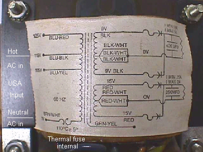
In the pic the AC line input is shown in the correct position for USA power which is often referred to as 110,115 or 120, depending on whose schematic you are reading or in this case, the layout right on the transformer itself. Now if we move our known 115VAC hot wire to the 125VAC input tap above it, we are supplying an input potential that is lower than the 125 volts needed to produce the required results on the secondary winding, ergo, the secondary windings are also outputting lower voltages.
This is the desired effect for the Galaga in question. Although the xformer in the pic does not have an added 1:1 isolation output, let's assume it does for purposes of comparison. When the line voltage is applied to the proper tap, you would have 115VAC isolated to the monitor. After moving the hot wire to the 125V tap, your results would be 100VAC...+ or - a volt or two...and the other secondary voltages, would also be reduced to dual 7V CT & 12V CT outputs...still plenty to rectify & supply regulator inputs...so the game should function with the correct input voltages to the pcb & to the 100VAC Nintendo monitor.
This xformer has a 105VAC hot tap and if you move your hot to it, you will be placing the undesirable voltages on everything connected to the secondary windings since you will be supplying it with more voltage than the tap requires.
I'm trying to keep the technical jargon down, the formulae out and get this into the simplest form, as I realize that the majority of readers are collectors who are by day, doctors, nurses, dentists, truckdrivers, mail carriers, programmers, engineers...well y'all read everyone's occupations in the RGVAC thread awhile back, so I'm sure you know the rest.
Now...onto what I found on Dejanews...a quiz on xformers by Brien King. Alrighty then...it's been a hundred years since college, but I'll give it a try in basic terms...especially after reading some of the answers :( I'm sure things have not changed that much over the years.
1) What does the size of the transformer mean? Does bigger mean more amps, volts, etc...?
The physical size doesn't really mean a thing to our applications, other than that they are most likely a multiple output xformer with a host of input taps for line in operating voltage if they are huge. Some of the very large xformers have less than a 1 Amp isolated output to run the monitor, while some of the medium sized ones have 1.5 amp to run the monitor. The difference is in the number of coils, called windings, and in the gauge of wire (determines the amps of that winding) used to wind these coils that are used to obtain other usable sources of AC power.
If you were to line up 5 1:1 isolation tranformers, then the larger one of all of them, would most likely be the highest amperage one, all things considered, but not necessarily so. The volts have no correlation to size. You have very small xformers in switching PSs & very large ones in Taito's vid games, but they both require an input of 115VAC & output the necessary voltage & amperage to the circuits they operate. Some of the secondary windings on the very large xformers only output 6.3 VAC at around 500 milliamps...just enough to operate a couple of coin door lamps.
In other fields, where a 230 volt 10 amp output might be required, or some other heavy duty output, you will see a greatly enlarged & heavy xformer. Just isn't applicable to vid game operation.
2) Whats the difference in the number of inputs and outputs?
Multiple primary windings are indeed used in vids. One example would be the WMs series where they use a jumper to feed 115VAC to each of twin windings. By replacing the jumper with a different configuration, the twin windings are joined together to accept a 230VAC input.
Atari offers another twin winding primary that has input selection via a jumper plug. I've seen many come into the shop with a small pic in the center, or not working at all...sometimes with a lot of damage...due to an op changing the jumper plug while attempting to repair something else. I would assume a blown fuse, which would disable the machine & might cause him to try another of the jumpers in hopes of getting it going....once the fuse was found & replaced, he'd be left with the wrong jumper plug & assume it was the fault that caused the fuse to blow. In the US, the jumper plug should be the one with yellow wires which route the incoming AC line to operate the xformer at 120VAC. The other option plugs usually cable tied together are Violet/100V.. ...blue/220V.....brown/240V.
The number of outputs are determined by the number of secondary windings in the transformer...some with a CT (center tap to divide the whole voltage, i.e., 30VAC-CT would be 2 15VAC in respect to the center tap or 30VAC from one end to the other) that is not used, adding leftover taps/terminals. Typically, you will find 2 taps for 115V isolation to monitor, 2 in the neighborhood of 15v for rectifying down to a 12VDC for the sound circuits, generally, and possibly 4 at about 7VAC.....one pair for -5VDC feed & one pair for +5VDC feed. Some go on to add a winding for 6.3VAC to directly feed the coin door lamps, while still others add a winding to operate coin lockout coils on the coin door or other circuits within the game. All in all, you can add up a whole parcel of terminals pertruding from that huge hunk of metal....all at the whim of the designer.
3) Is it possible to get them backwards? I.e. reverse the input/output sides.
It sure is! Each and every tap has it's own unique number to identify which winding it is inside the xformer. Your xformer should have the number terminal it is marked right on it. If not, they usually have color coded wires & you'll need a schematic to identify them, especially with the big multiple ones, which require the external jumper plugs to route wiring of the internal windings. On smaller xformers it is usually pretty easy to find the input...most often on one side...and the outputs coming from the opposite side. These usually have 6" wire leads exiting & are color coded & grouped together so that you could measure the voltages to determine the output values. Keep in mind, that if you do not know what the xformer is used in, you'll not have a way to determine it's amps by this method.
Single unit monitor isolation xformers are easy to determine the primary winding from the secondary winding via an ohmmeter. Although they are a 1:1 ratio, and both windings should measure equally, in the real world, the primary will be as much as 1 ohm less than the secondary going up to the monitor. 5 to 6 ohms primary....6 to 7 ohms secondary. The primary winding is almost exclusively on the bottom, with the secondary to the top on 1:1 ratio xformers, but on a step-down isolation xformer,like the 1.2:1 100VAC output, it is just the opposite, although the 1.2:1 can be reversed to supply a 115VAC monitor with the proper voltage from a Nintendo 100VAC output xformer. This should only be done with a single unit isolation xformer as the windings will be made up from the same gauge wire, as opposed to a winding that will only handle 250ma, and there are no other seconday windings to contend with.
Hooking up the AC line input to a 6.3VAC output could prove to be quite a spectacular show. More food for thought when attempting a guess at what a pair of terminals are used for.
4) Is there a difference between using the top side of the transformer and bottom side? In the Williams games they have Isolation Transformers that have Inputs and Outputs on both the top and bottom of the transformer. Which should be used in which cases or does it even really matter?
The top side & bottom are not relative in & of themselves. These are simply the best exit points for the various coils inside the xformer. Each winding will generally be located together, e.g., 7 & 8 will constitute a coil, or it could be 7 & 9 with 8 being an unused CT terminal.
I've accidently covered this in Qs 1 thru 3, but the isolated output in WMs does have 2 outputs...1 for the monitor & 1 for the marquee lamp...that are electrically the same point at the xformer, terminals 9 & 10, however, at the connector 6J1 they divide and 9 & 11 are electrically the same & 10 & 12 are electrically the same, with 9 & 10 being the marquee lamp, and 11 & 12 being the monitor. You can swap them, as long as the pairs are kept together. Again, everything else does really matter.
5) Are ALL the outputs isolated from their inputs or are some just pass through?

There are many types of transformers & the ones that are used in the vid games are isolated step-down, step-up & true "isolation (1:1)". Since HS, many moons ago, and my first electronics instructor, Ben Woods, I've always heard & classified myself, all isolated transformers as isolation transformers by virtue of their construction...all little coils to themselves...depending on induction of AC (alternating current) at the primary taps to produce an output from them. I say true isolation above, as the term was used to signify a 1:1 transformer whereby you got out, what you put in, but today there are isolation xformers marketed with ratios from 1.3:1 to 1:1.3, which simply means that they slightly step up or down the resulting output to meet the circuit's requirements.....be it monitor, power supply or some equipment used in a hospital.
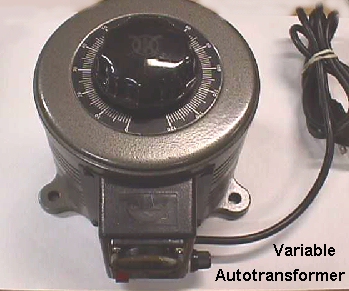
Autotransformers are ones in which one of the primary input winding terminals is also used as a secondary tie point. I just read that my bud, John, seemed to think that the WMs xformer was a type of autoxformer, but since it does not share a primary & secondary terminal & is totally isolated, I would have to disagree with that, and I don't believe that any were ever used in the construction of vid games. The most common use of these today, at least as it pertains to this field, is in the variable transformers that are sold pretty much nationwide as a piece of test equipment best used in finding circuit shorts, and one must remember to also use an isolation xformer in conjunction with these....especially on monitor work.
I just took a look for any posts I might have missed and came up with Dick Merryman's post...excellent job, although in his added comments he missed a trick question that pertains to newer vids...not that I haven't made any errors here, as matter of fact, with only one eye open at this point, you may be missing every other letter I typed :)
Dick Merryman wrote:
- Are any of the outputs of the isolation transformer DC?? Not by a long shot.
Transformers work only on AC.
This used to be true up until about the turn of this decade, at least that is when I got my first of many tricky little xformers. It seems that someone has gotten the bright idea of installing diodes inside of the metal cased transformers, sandwiching them in between 2 layers of insulating fish paper. The first one I got in was in a gaming vid & I immediately jumped to the conclusion that I had an open secondary winding....no AC out....wrong, but right. There was no AC out, but there was a DC output. I hope they haven't thought about utilizing all this surface mount technology to a point where they can house an entire power supply inside a xformer shielding case, sandwiched in between a couple insulators.
Happy Gaming...........