Let me start with a little history & you can skip on by this if you want. In the 1970s & early 1980s we had no vid game system in place such as the JAMMA system of today, so our test jigs were very basic with each portion terminating to a specific plug, i.e., a 15 pos Molex connector for input to control panel, a 9 pos for video input, dual 6 pos Molex for power output & a 2 pos for the speaker...the reason for breakdown was to utilize, e.g., the speaker for testing an amp, without needing to use another 15 position plug for only 2 wires.
You can see where this is going, each game pcb that came into the shop, had to have a hard wire configuration made up from whatever I/O connectors that that specific game had, to the test jig Molex I/O. Needless to say 4' wiring harnesses were piling up as each different pcb came in to be tested or worked on.
Now along comes Konami with a system that our first 18/36 harness built would work with many boards & they kept coming...more & more...WOW a unified system. Let's run with it. Now we have to make adaptors from game X, Y & Z as they come in to adapt to a Konami harness & we can use adaptor cards. Can it get any better?
Well, of course it could, and Konami..the innovator of the concept..had to join ranks with the others to satisfy larger I/O needs and bigger & better vid games in this new fangled system called JAMMA. Umph! Now we need to go with JAMMA adaptors & hook up a JAMMA harness to every jig in the shop.
Well I started by having the adaptor card fingerboards made right here in New Orleans where everything cost a fortune, and by the end of 1986 most all the old commonly used harnesses had been adapted to this new system. The first design....similar to the ones I use now from Andy's House of Adaptors....was off by a bit, since I only made provisions for up to a 22/44 pos edge connector on the adapted side :( Who knew that mfgers would see this 28/56 connector as an opportunity to start making up their own pinouts to it...jeez...now I needed 28/56 to 28/56 & they wanted my first born child and the next ten years profits to make up the fingerboards for me. My first reaction was to say, "excuse me, but I don't want them already prewired" to which I was given a song & dance about the cost of design going up & etc..etc.
Enter my savior...John Robertson of John's Jukes had already gotten some made up & they would save me $2 on each one at $10 each at that time. Well, the adaptors continued to be made for each game that was to go on location that was not JAMMA. Many a Ms Pac-Man & Galaga were adapted to 25" JAMMA cabs & put on location.
1999 & now collectors & just plain game players want to adapt games to JAMMA cabs and Ms Pac-Man seems to be one of the big stumbling blocks that was overcome back around mid 1986 and without all this damage & hacking to the pcbs. An op could take his Pac series pcb with him & put it in a dedicated game or a JAMMA cab & have it work equally well with only sometimes having to turn the +5 volts up a tad...and they marked one that had to go up, so that when the next route collector went to change the pcb, he knew to turn the voltage down. This was not very often, and we were using 7 amp switching power supplies at the onset...today there is no need to set the 5 volts high with these 15 amp power supplies.
 I've tried to explain this to several people, but they can't get by the theory factor, which I threw out over 40 years ago when I got my first job working for a distributor. They said if you want to continue working here, you're going to have to get all those college ideas out of your head and start from scratch in the real world. I did & have owned my own businesses for 40 years now, so they were right.
Now I have this Sony digital camera to take take pic's as I go, so that it is seen, as well as read. Here's how to make an adaptor for Pac series. BTW: In electronics, it is adaptor rather than adapter which might apply to a plumber's trade or others, although I guess it really doesn't matter, since anyone in electronics is going to know what you are talking about.
The one thing you want to do when making an adaptor for a Pac series is to put plenty of 18 gauge wires to ground & to the 5 volt inputs (old 7VAC) as the more you put, the easier the voltage/current travels to the pcb by the simple ohm's law principle of parallel resistances lessening the total resistance, which people find hard to believe in these little wires, but there is no place that proves this theory any better than on these adaptors.
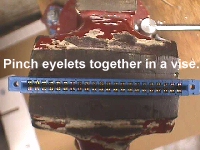
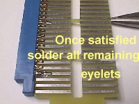 The pic's above are self-explanatory and are the first steps to getting this adaptor under way. In the pic at the left, you will note that the tip of the pliers is underneath the card to hold it level. You can see it better in the pic on the right which shows it after being tacked in place first before continuing to solder all connections..just in case you need a little adjustment. Be sure to tack both sides...one at each end & one in the middle.
TIP: This applies to any adaptor cards you are building....if you get the pinout printed out on an 8.5x11 piece of paper you can fold it right down the middle so that you only see the side you are working on...solder or parts...and this reduces the chance of error by a large margin.
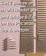 The foolproof way is to get an old labeled JAMMA connector & place it on the JAMMA side of the card, like in the pic to the left. Make sure that you have the parts side up for the Pac side & you'll need the pinouts for it, as well, but before you get started, you have to make two bridges on the adaptor card. One shorts out C-D-E on the parts side, and the other shorts out 3-4-5 on the solder side. It's easiest to count up from the bottom of the actual fingerboard to positions 6-7-8 on both sides. Perhaps the pic will be a more concise way to show it. As you see in the pic in the upper right, it is much easier to look at it than it is to describe it. Do the same on the flip side. Once this is done, you can run the power wires as below. I'll put pinouts to power wiring, but the rest will have to be done from a pinout sheet.
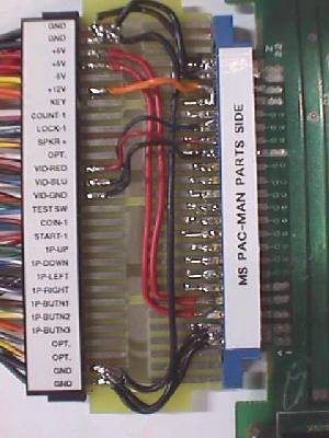
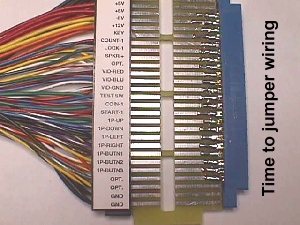
In the pic on the left you will see that the DC power lines are easiest to run first. On the parts side as depicted, there are 3 ground wires leaving the Jamma pins 27/28 made into a single pad with 2 lines going to A/B on the Pac side, also padded to form a single pad, and the 3rd wire goes Jamma 1/2 which ties the 2 ground pads together & then it also has 2 grounds leaving the Jamma 1/2 to go to the Pac side pad of Y/Z. The 2 red 5 volt lines form a pad at the Pac side C/D/E & run up to the Jamma side 3/4 pad. Lastly, we have the 12 volt orange wire going from Jamma 6 to Pac W/X pad. I've found that even most techs stop at this point & figure that there is enough wired in for power needs....not true...much more is needed. As I said, you want more parallel lines in, the more streams you can put into the lake (PAC),the more you will lessen the resistance by dividing up the load going into the Pac board. This will make the job of your switcher very easy to do with no strain at all and providing ample power to drive the board. When finished, this also produces a side effect of reducing all the heat that eminates from the board itself, especially reducing heat off from the rams & proms which often times are hot enough to burn you.
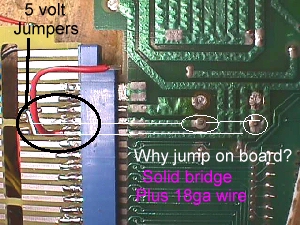
Lets power out the solder side now. In the pic to the left, you'll see what the solid jumpers & 18 gauge wire do at C-D-E & at 3-4-5...essentially the same thing you are doing by jumpering diodes on the Pac board itself, but without harming the integrity of the board. Ok...the backside power wiring is a little different. Starting with the ground pad at Pac 1/2, the first wire goes to the Jamma pad e/f while the second wire goes to Jamma pad A/B. The ground pad at Pac 21/22 also splits with one wire going to Jamma pad A/B while the second wire goes to Jamma pad e/f. A crisscross ground layout with all double connections made into a single pad. The 2 red 5 volt lines on Pac pad 3/4/5 run up to the Jamma pad C/D where there is also a 3rd red wire leaving this 5 volt pad & connecting to the Pac single pad at position 18. All that is left for power now is the second 12 volt input which goes from Pac pad 19/20 to the Jamma single pad F.
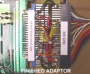
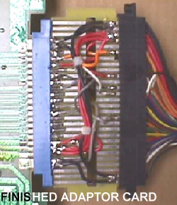
Well...filling in the rest of the wiring is fairly easy & straight forward & a 20 gauge wire should be ample for any remaining connections. After I finished this one I performed tests on it in 3 Jamma cabs with the same results in each one with different Jamma pcbs. The first test was with a Double Dribble whereby I set the power supply to deliver 5.00 volts to the edge connector. I then powered down & moved the Jamma harness to the Pac board & repowered & measured the voltage at the Pac edge connector. It measured 5.10 volts & the Pac played fine & ran cool. I repeated this with a Plotting & a Neo 1-slot with the exact same results. With the parallel system in use, I actually deliver more voltage to the Pac board than I do to the Jamma boards.
The parts necessary to do this are on the "Parts Page". If you want, I can make you up a kit of the fingerboard card, 22/44 pin edge connector...SE type...and a bag of new wire clippings from harness building leftovers for $8 plus $5 shipping USPS Priority.
Happy Gaming...........